What is Amplification?
Amplification of a stable, biased triode is like making something louder or stronger. It’s when you increase the volume or power of something, such as a sound, signal, or idea. It’s like turning up the volume on a speaker to make the music louder or using a magnifying glass to make small writing on a page bigger. So, amplification is about making things more noticeable or powerful.
Stable Bias Triode:
A triode is a specialized electronic amplifying device commonly found in vacuum tubes or early transistor circuits. The term “stable bias” refers to a biasing arrangement in the circuit that ensures stable operating conditions for the triode. This stability is essential for the reliable functioning of electronic devices.
- A triode is a type of electronic amplifying device, often used in vacuum tubes or early transistor circuits.
- “Stable bias” typically refers to a biasing arrangement in the circuit that ensures stable operating conditions for the triode.
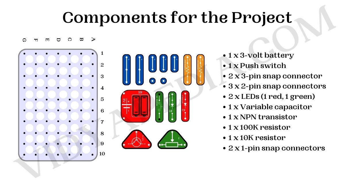
Components for the Practical or Project

- 1 x 3-volt battery
- 1 x Push switch
- 2 x 3-pin snap connector
- 3 x 2-pin snap connectors
- 2 x LEDs (1 red, 1 green)
- 1 x Variable capacitor
- 1 x NPN transistor
- 1 x 100K resistor
- 1 x 10K resistor
- 2 x 1-pin snap connectors
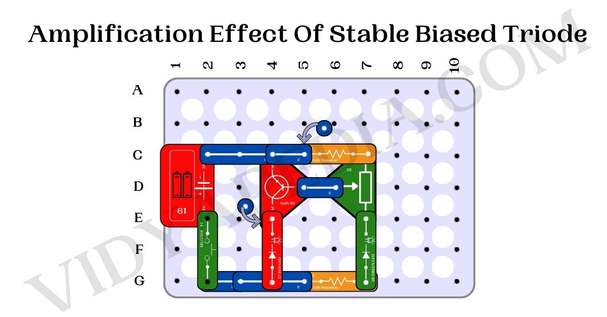
Steps for making project On Junior BreadBoard

- Connect the battery’s positive terminal to the E2 pin and the negative terminal to the C2 pin on the breadboard.
- Connect a two-pin snap connector from the G2 pin to the G3 pin.
- Connect the push switch between the E2 and G2 pins.
- Connect the NPN transistor with its collector (C) on the E4 pin, emitter (E) on the C4 pin, and base (middle pin) on the D5 pin.
- Use a three-pin snap connector to bridge the C2 and C4 pins.
- Connect a 10K resistor between the G5 and G7 pins.
- Use a three-pin snap connector to bridge the G3 and G5 pins.
- Connect a one-pin snap connector to the E4 pin (top of the NPN transistor).
- Connect the red LED with the longer leg (anode) to the G4 pin and the shorter leg (cathode) to the E4 pin, placing the LED in the upward direction.
- Connect the variable capacitor with one leg on the E7 pin, the other on the C7 pin, and the middle pin on the D6 pin.
- Use a two-pin snap connector to bridge the D5 and D6 pins.
- Connect a one-pin snap connector to the C-5 pin on the breadboard.
- Connect a 100K ohm resistor between the C-5 and C7 pins.
- Use a two-pin snap connector to bridge the C4 and C-5 pins.
- Connect the green LED with the longer leg (anode) to the G7 pin and the shorter leg (cathode) to the E7 pin.
Working of the circuit
When you turn on the switch and tweak the potentiometer, notice the green LED subtly changing while the red one on the collector side varies noticeably. Sliding down almost turns it off, but going up in that range keeps it bright consistently. This experiment helps you understand how the potentiometer affects the circuit and how LEDs respond. It’s like discovering how different parts work together in electronics.
Application of amplification in a stable biased triode
- Audio Amplification: Enhances weak audio signals for louder and clearer sound in radios and amplifiers.
- Signal Processing: Crucial in amplifying and conditioning signals for effective communication in various systems.
- RF Amplification: Boosts radio frequency signals in radio receivers and transmitters for improved transmission.
- Television systems amplify video and audio signals, ensuring a clear and vibrant display on TV screens.
- Instrumentation Amplifiers: Accurately amplifies sensor signals in measuring and testing equipment.
- Guitar Amplifiers: Used to amplify weak guitar signals, creating powerful and distinctive sounds in music.
- Medical Equipment: Utilized in medical devices like ECGs and ultrasound machines for clear and accurate readings.
- Transistor Amplifier Replacement: Acts as a replacement for ageing transistors in older electronic systems, extending equipment lifespan.
- Antenna Pre-amplification: Boosts weak incoming signals in the pre-amplification stage of antennas for better reception.
- Educational Projects: Demonstrates amplification principles in hands-on electronic projects for student learning.
Frequently asked Questions
What is amplification?
Increasing the strength in the form of the sound signal, or the (y-axis) peak value of any signal.
Why is stable biasing important in this circuit?
A stable biased triode helps to maintain the current only when the input signal is given to the transistor.
What happens during potentiometer adjustment?
Changing the value of the potentiometer or adjusting its knob will result in a change in the intensity of the LED connected to the circuit.
What are the applications of amplification in the above Circuit?
Applications include audio amplification, signal processing, RF amplification, television systems, instrumentation amplifiers, guitar amplifiers, medical equipment, transistor replacement, antenna pre-amplification, and educational projects.


