Air break switches are vital components in electrical distribution networks, particularly for outdoor installations. They are used to control and isolate sections of the electrical network. Here’s a detailed, easy-to-understand overview, including specific details for both 11 kV and 33 kV systems.
What are air break switches?

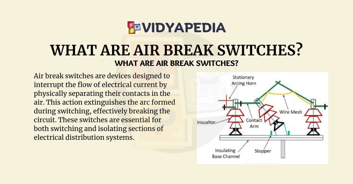
Air break switches are devices designed to interrupt the flow of electrical current by physically separating their contacts in the air. This action extinguishes the arc formed during switching, effectively breaking the circuit. These switches are essential for both switching and isolating sections of electrical distribution systems.
Applications and Benefits of Air Break Switch

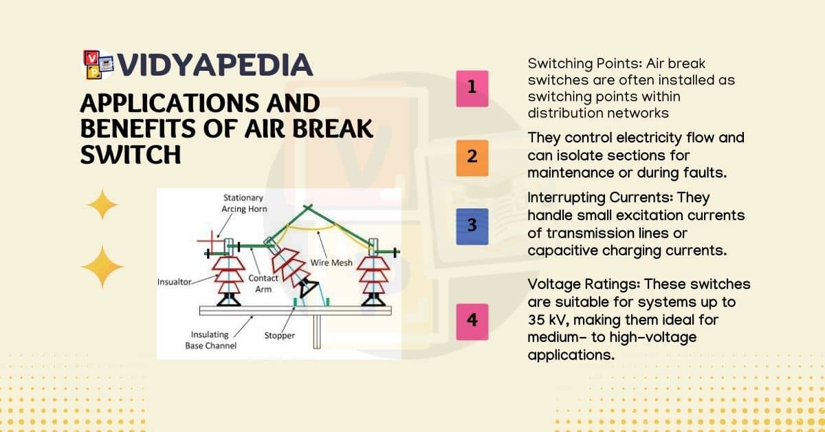
- Switching Points: Air break switches are often installed as switching points within distribution networks. They control electricity flow and can isolate sections for maintenance or during faults.
- Interrupting Currents: They handle small excitation currents of transmission lines or capacitive charging currents.
- Voltage Ratings: These switches are suitable for systems up to 35 kV, making them ideal for medium- to high-voltage applications.
Read More Electrical Engineering
Types of Air Break Switches
Air break switches come in two main types, each serving different operational needs:
Single-Pole Air-Break Switch
- Function: Opens or closes a single conductor.
- Usage: Ideal for individual phase control.
- Operation: Manages a single phase independently.
Gang-operated air-break switch
- Function: Simultaneously opens or closes multiple conductors.
- Usage: Perfect for three-phase systems where all phases need to operate together.
- Mechanism: All phases are interconnected and operate together. These switches can be installed horizontally or vertically and are typically mounted on pole tops or within pad-mounted enclosures.
Installation and Operation
- Mounting Options: Air break switches can be installed horizontally or vertically, depending on site requirements.
- Location: Typically placed on pole tops or within pad-mounted metal enclosures for protection and accessibility.
- Operation Methods: Can be operated manually or through a motorized mechanism for remote control.
Specifics for 11 kV Air Break Switches with Polymeric Insulators
These switches are built for outdoor installation and ensure reliable operation in commercial power distribution systems. Key features include:
- Triple Pole Construction: Controls three-phase systems securely.
- Manual Operation: Includes a locking mechanism for maintaining ON or OFF positions, ensuring safety and control.
- Durable Materials: Contacts are made from hard-drawn copper and silver-plated for enhanced conductivity and durability.
- Adjustable Phase Spacing: Spacing between phases can be adjusted between 600 mm and 700 mm.
- Polymeric Insulators: These insulators provide high mechanical strength and electrical insulation, making them ideal for outdoor environments.
Specifics for 33 kV Air Break Switches
For higher voltage applications, up to 33 kV, these switches share similar features but are designed to handle higher power and more demanding environmental conditions:
- Outdoor Installation: Designed for outdoor environments, mounted on poles or within enclosures.
- Switching and Isolation: Used to interrupt and isolate parts of the distribution network for safety during maintenance and faults.
- Voltage and Current Handling: Capable of managing higher excitation and capacitive currents associated with higher voltage systems.
Technical Specifications for 11 kV Air Break Switches
Scope
This specification covers the design, manufacturing, testing, inspection, packing, and delivery of 11 kV Air Break Switches for outdoor installation, ensuring they meet high engineering standards for continuous commercial operation.
Applicable Standards
- IS 9920 (Parts 1 to 4)/1981: General requirements and performance specifications.
- IS 2633/1986: Galvanizing standards for corrosion protection.
- IS 2544/1973: Requirements for insulators.
- IEC 61109: Standards for polymeric insulators.
System Particulars
- Nominal Voltage: 11 kV
- Highest Voltage: 12 kV
- Discharge Test Voltage: 9 kV
- Frequency: 50 Hz (with variations from 47 Hz to 51.5 Hz)
- Grounding: Effectively grounded
- Phases: Three-phase system
Current Density
Maximum allowable current density:
- Copper: 2.00 Amps/sq. mm
- Aluminum Alloy: 1.25 Amps/sq.mm
- Gun Metal Base: 1.63 Amps/sq.mm
Constructional Features
- Triple-pole construction ensures secure operation for three-phase systems.
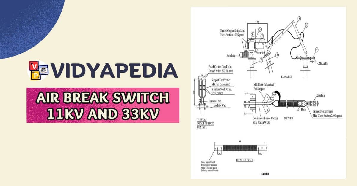
- Insulators: Uses three 11 kV polymeric insulators per phase, mounted on metal channels.
- Manual Operation: A locking mechanism for secure ON/OFF positions.
- Contacts: Made from hard-drawn copper, silver-plated for durability.
- Gun Metal Base: Durable and provides good electrical properties.
- Adjustable Spacing: Between 600 mm and 700 mm for flexible installation.
- Coupling Rod: Galvanized iron to prevent corrosion.
Testing and Inspection
- Type Tests: Verify design and performance, including temperature rise, current handling, insulation, and mechanical endurance.
- Routine Tests: are conducted on each unit to ensure they meet essential requirements before shipping.
- Acceptance Tests: Performed on samples from each batch to ensure compliance with standards.
Challenge Clause
The purchaser reserves the right to re-test the switches to ensure compliance. If they fail, the entire lot may be rejected and must be replaced at the supplier’s cost within thirty days.


