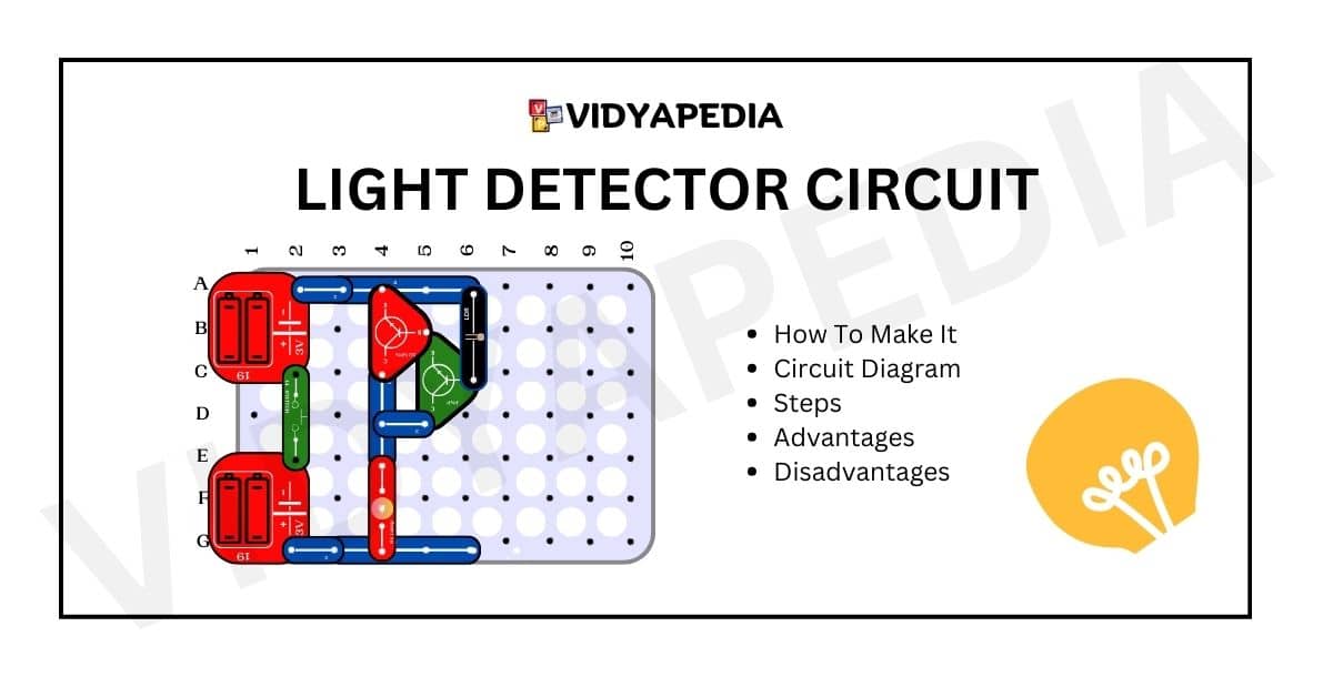
A light detector circuit is an intelligent electrical system that allows machines to “see” and respond to changes in light. Consider it the eyes of a robot or a smart device that can detect when it is bright or dark. The photoresistor, a type of sensor that alters behaviour when exposed to light, is a crucial component in this circuit. When it is bright, the photoresistor allows more electricity to flow; when it is dark, it prevents energy flow.
This miraculous circuit functions similarly to a little brain, making decisions based on the signals from the photoresistor. For example, solar trackers allow solar panels to follow the sun and absorb as much sunlight as is feasible. This increases the efficiency of solar energy systems. Daily devices such as automatic lights, streetlights, and security systems also use light detector circuits. When it gets dark, these circuits notify the lights to switch on, making our lives safer and easier.
In basic terms, a light detector circuit is a helpful wizard that uses light to improve things—conserving energy, increasing efficiency, and brightening our modern world!
Look For More Content At Botorzo
What is a light detector circuit?
A light detector circuit is a system that reacts to changes in light intensity. It activates when exposed to light and deactivates in darkness. This feature makes it useful in applications like automatic lights and solar trackers, where it optimizes energy usage based on ambient light conditions.
Components Required For Making Light Detector Project
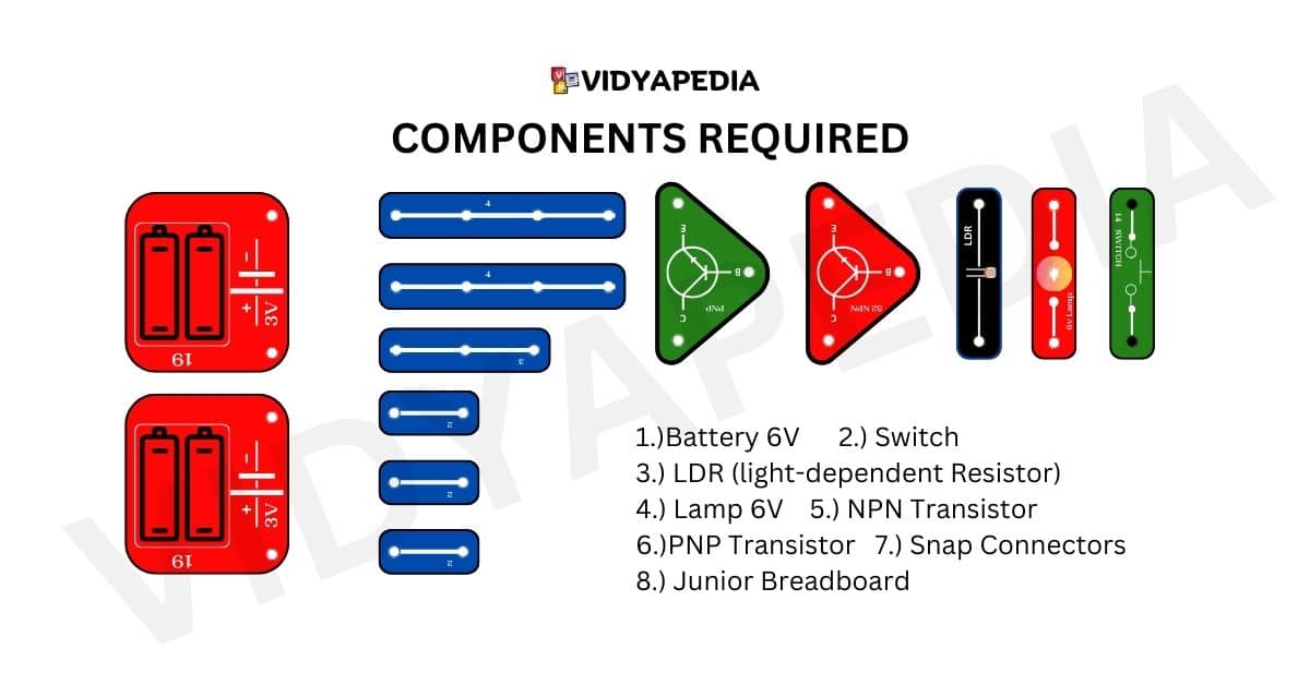
The components required are:
- Battery 6V
- Switch
- LDR (light-dependent Resistor)
- Lamp 6V
- NPN Transistor
- PNP Transistor
- Snap Connectors
- Junior Breadboard
Circuit Diagram
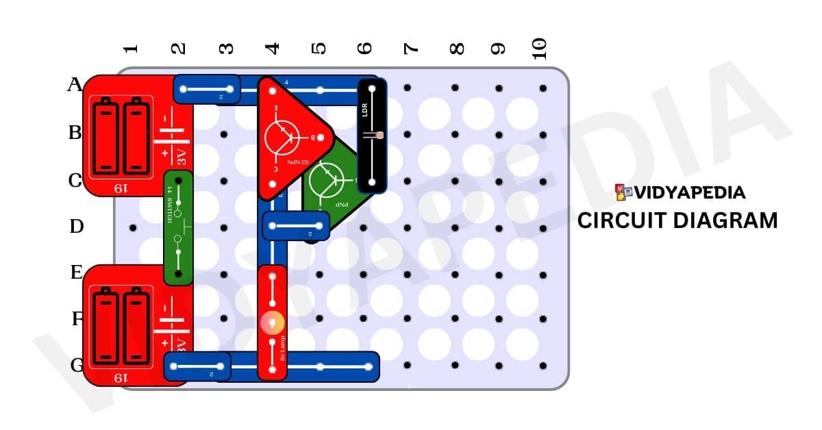
Steps For Making a Light Detector Circuit
- Connect the positive terminal of the first battery to C2 and the negative terminal to pin A2.
- Connect the positive terminal of the second 3-volt battery to pin G-2 and the negative terminal to pin E2.
- Place a switch between pins C2 and E2.
- Attach a 4-pin snap connector to A3 and A6 on the breadboard.
- Add another 4-pin snap connector to pins G3 and G6 on the breadboard.
- Connect a 2-pin snap connector to pins A2 and A3.
- Attach two 2-pin snap connectors to pins G2 and G3.
- Connect a 3-pin snap connector to pins C4 and E4.
- Integrate a 6-volt lamp, linking it to pins E4 and G4.
- Connect a PNP transistor with the middle pin on C6, the emitter on B-5, and the collector on D5.
- Connect an NPN transistor with the middle pin on B5, the emitter on A4, and the collector on C4.
- Use a 2-pin snap connector between pins D4 and D5.
- Connect an LDR (light-dependent resistor) between pins A6 and C6.
Working Of Light Detector Circuit
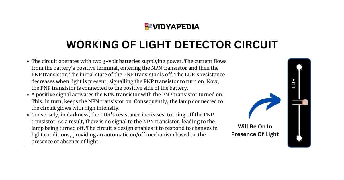
The circuit operates with two 3-volt batteries supplying power. A stable-based triode is used here. The current flows from the battery’s positive terminal, entering the NPN transistor and then the PNP transistor. The initial state of the PNP transistor is off. The LDR’s resistance decreases when light is present, signalling the PNP transistor to turn on. Now, the PNP transistor is connected to the positive side of the battery.
A positive signal activates the NPN transistor with the PNP transistor turned on. This, in turn, keeps the NPN transistor on. Consequently, the lamp connected to the circuit glows with high intensity.
Conversely, in darkness, the LDR’s resistance increases, turning off the PNP transistor. As a result, there is no signal to the NPN transistor, leading to the lamp being turned off. The circuit’s design enables it to respond to changes in light conditions, providing an automatic on/off mechanism based on the presence or absence of light.
Real-life Applications
- Outdoor lighting: When it gets dark, the streetlights or garden lights turn on automatically.
To save electricity, lights are turned off when there is enough daylight. - Security systems integrate light detectors into motion-activated lights to improve security.
Responds not only to motion but also to ambient lighting conditions. - Dusk-to-Dawn Lamps: Light detectors are used to enable automatic on/off functionality.
Ensures a smooth transition between day and night lighting. - Photovoltaic Solar System: Uses light detector circuits in solar trackers for panels.
Ensures that panels follow the sun’s position, improving exposure for greater energy efficiency. - Electronic gadgets: implement light detectors in devices such as cell phones.
Adjusts screen brightness based on ambient light conditions to improve user comfort and save energy.
Advantages of Light Detector Circuits
- Improve energy efficiency by adjusting lighting based on environmental circumstances.
- Enable autonomous systems with minimum human interaction.
- Contribute to cost savings, especially in applications such as street lighting.
- Increase security by responding to both motion and ambient light changes.
- Align solar panels toward the sun to maximize their efficiency.
Disadvantages of Light Detector Circuits
- Sensitive to environmental changes, resulting in unintentional activation or deactivation.
- Dependency on a light source may not be effective in complete darkness.
- Because of their exposure to the environment, outdoor detectors may require regular maintenance.
- Applicability is limited in instances involving absolute darkness.
- Intricate circuits require careful calibration due to their complexity of design.
Frequently Asked Questions (FAQ)
What is a light detector circuit?
A light detector circuit is an intelligent electrical system that responds to changes in light, serving as the eyes of machines to automate processes based on light intensity.
What components are needed for making a light detector project?
Components include a 6V battery, switch, LDR (light-dependent resistor), 6V lamp, NPN and PNP transistors, snap connectors, and a breadboard.
How does the light detector circuit work?
The circuit uses two 3-volt batteries to power NPN and PNP transistors. Light presence activates the transistors, turning on the lamp. Darkness turns off the lamp, providing automatic on/off based on light conditions.
What are the advantages of light detector circuits?
Light detector circuits improve energy efficiency, enable autonomous systems, contribute to cost savings, enhance security, and optimize solar power generation by aligning panels with the sun.
Are there any disadvantages to light detector circuits?
Yes, they can be sensitive to environmental changes, depending on a light source, may require regular maintenance, have limited applicability in complete darkness, and their intricate design demands careful calibration.